


Need better scanning performance?
CaptureVisionTemplate Object
A CaptureVisionTemplate object is the entry point of a parameter template in Dynamsoft Capture Vision (DCV) SDK.
Example
{
    "Name": "CV_0",
    "ImageSourceName": "ISA_0",
    "ImageROIProcessingNameArray": ["TA_0"],
    "SemanticProcessingNameArray": ["SP_0"],
    "OutputOriginalImage": 0,
    "MaxParallelTasks": 4,
    "MinImageCaptureInterval": 0,
    "Timeout": 500
}
Parameters
| Parameter Name | Type | Required/Optional | Description |
|---|---|---|---|
Name |
String | Required | The unique identifier for this template. |
ImageSourceName |
String | Optional | The name of the ImageSource object defining the input source. |
ImageROIProcessingNameArray |
String Array | Optional | Array of TargetROIDef object names defining recognition tasks on image ROIs. |
SemanticProcessingNameArray |
String Array | Optional | Array of SemanticProcessing object names for post-processing tasks. |
OutputOriginalImage |
Integer | Optional | Whether to output the original input image (0 or 1). |
MaxParallelTasks |
Integer | Optional | Maximum number of parallel tasks for the DCV runtime. |
MinImageCaptureInterval |
Integer | Optional | Minimum time interval (in milliseconds) between consecutive image captures. |
Timeout |
Integer | Optional | Maximum processing time (in milliseconds) per image. |
Input Source Configuration
The ImageSourceName parameter references an ImageSource object defining the image input source. When DCV starts capturing, it parses the ImageSource parameter, converts it into an Image Source Adapter (ISA) object, and continuously obtains images from it.
Captured Output Configuration
OutputOriginalImage, ImageROIProcessingNameArray, and SemanticProcessingNameArray control the captured output, organized as a CapturedResult interface in DCV. CapturedResult represents a set of all captured result items on an image. Each type of result item represents the output of different task types. The following figure lists the relationship between DCV output parameters and output results.
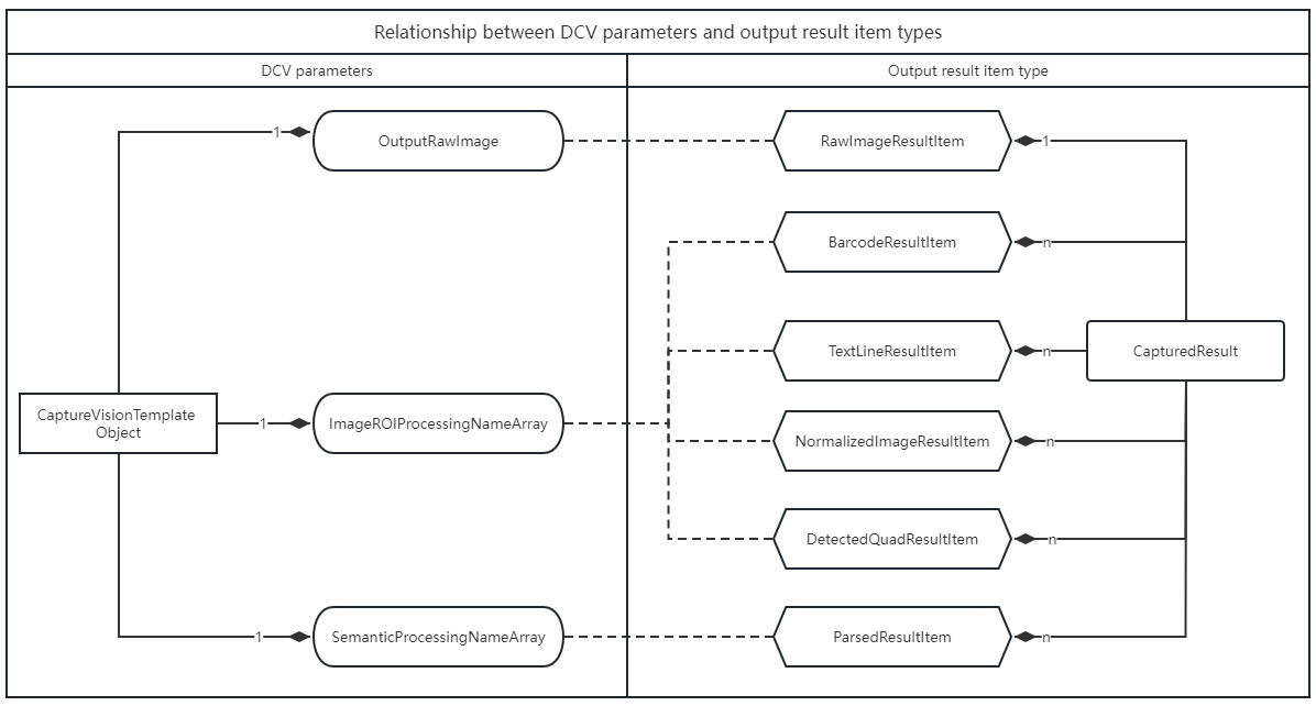
Parameter and result relationships:
ImageROIProcessingNameArrayproducesBarcodeResultItem,TextLineResultItem,DetectedQuadResultItem, andNormalizedImageResultItemSemanticProcessingNameArrayproducesParsedResultItemImageROIProcessingNameArrayreferences one or moreTargetROIDefobjectsSemanticProcessingNameArrayreferences one or moreSemanticProcessingobjects
Core Design of TargetROIDef Object
The TargetROIDef object specifies one or more recognition tasks to be performed on regions of interest (ROIs) within an image. In simple terms:
TargetROIDef = Recognition Task Definition + Spatial Location Definition
Key Concepts
| Concept | Description | Example Explanation |
|---|---|---|
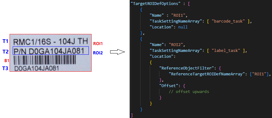
| Recognition Tasks | Tasks include barcode recognition, label recognition, document boundary detection, etc. | ROI1 and ROI2 are two TargetROIDef objects. Task barcode_task is configured on ROI1 and task label_task is configured on ROI2. |
| Atomic Result | Atomic result of recognition task output. Can be a color detection region, barcode, text line, table cell, detected quadrilateral, etc. | T1, T2, T3 are three TextLineResultItem objects, and B1 is one BarcodeResultItem object. |
| Spatial Location | A Location configured on a TargetROIDef may generate zero or more target regions on which to perform recognition tasks. |
ROI1.Location is null, generating one target region. ROI2.Location is an upward offset relative to ROI1 output regions. |
| Reference Region | A physical quadrilateral region. Two types: entire image region and atomic result region. The former is the quadrilateral extent of the original image; the latter is the quadrilateral extent of each atomic result. | ROI1 has one reference region (entire image). ROI2 has three reference regions generated from T1, T2, T3. |
| Target Region | A physical quadrilateral region calculated from a reference region and offset. | ROI1 has one target region equal to the reference region. ROI2 has three target regions calculated by offsets from T1, T2, T3 quadrilateral regions. |
Workflow Design Based on Reference/Target Regions
Using recursive definition of reference relationships between TargetROIDef objects, complex workflows can be constructed for complex scenarios.
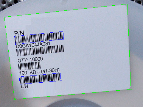
Example: Read barcodes below P/N and above L/N in the image. Positional dependencies:
- Target barcode location (blue box) can be calculated from text line locations (
P/NandL/N) - Text lines (
P/NandL/N) are on the first and fifth lines inside the label border (green box)
The following json is a parameter template fragment that configures ROI dependencies to solve the above problems.
{
    "TargetROIDefOptions": [
        {
            "Name": "ddn_roi",
            "TaskSettingNameArray": ["ddn_task"],
            "Location": null
        },
        {
            "Name": "dlr_roi",
            "TaskSettingNameArray": ["dlr_task"],
            "Location": {
                "ReferenceObjectFilter": {
                    "ReferenceTargetROIDefNameArray": ["ddn_roi"]
                },
                "Offset": null
            }
        },
        {
            "Name": "dbr_roi1",
            "TaskSettingNameArray": ["dbr_task"],
            "Location": {
                "ReferenceObjectFilter": {
                    "ReferenceTargetROIDefNameArray": ["dlr_roi"]
                },
                "Offset": {
                    "MeasuredByPercentage": 0,
                    "ReferenceYAxis": {"AxisType": "AT_EDGE", "EdgeIndex": 2},
                    "FirstPoint": [0, 10],
                    "SecondPoint": [100, 10],
                    "ThirdPoint": [100, 50],
                    "FourthPoint": [0, 50]
                }
            }
        },
        {
            "Name": "dbr_roi2",
            "TaskSettingNameArray": ["dbr_task"],
            "Location": {
                "ReferenceObjectFilter": {
                    "ReferenceTargetROIDefNameArray": ["dlr_roi"]
                },
                "Offset": {
                    "MeasuredByPercentage": 0,
                    "ReferenceYAxis": {"AxisType": "AT_EDGE", "EdgeIndex": 0},
                    "FirstPoint": [0, -50],
                    "SecondPoint": [100, -50],
                    "ThirdPoint": [100, -10],
                    "FourthPoint": [0, -10]
                }
            }
        }
    ]
}
In this configuration:
- Four
TargetROIDefobjects:ddn_roi,dlr_roi,dbr_roi1, anddbr_roi2 ddn_roidepends on the entire image regiondlr_roidepends onddn_roiwith null offset (same region)dbr_roi1depends ondlr_roiwith downward offsetdbr_roi2depends ondlr_roiwith upward offset
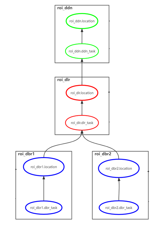
Construct a Dependency Graph
When DCV parses TargetROIDef objects, it constructs a directed dependency graph based on configured dependencies. Tasks execute in the order specified by the dependency graph.
Filter Out the Desired Reference Regions
In practical applications, a TargetROIDef may want to depend only on reference regions from another TargetROIDef that meet specific filtering conditions, such as text matching a regular expression or barcodes meeting a specific format requirements.
Based on the previous example, regular expression filtering conditions can be added to dbr_roi1 and dbr_roi2:
{
    "TargetROIDefOptions": [
        {
            "Name": "roi_dbr1",
            "TaskSettingNameArray": ["dbr_task"],
            "Location": {
                "ReferenceObjectFilter": {
                    "ReferenceTargetROIDefNameArray": ["roi_dlr"],
                    "TextLineFilteringCondition": {
                        "LineStringRegExPattern": "^P/N"
                    }
                },
                "Offset": {}
            }
        },
        {
            "Name": "roi_dbr2",
            "TaskSettingNameArray": ["dbr_task"],
            "Location": {
                "ReferenceObjectFilter": {
                    "ReferenceTargetROIDefNameArray": ["roi_dlr"],
                    "TextLineFilteringCondition": {
                        "LineStringRegExPattern": "^L/N"
                    }
                },
                "Offset": {}
            }
        }
    ]
}
Filtering logic:
roi_dbr1depends only on regions fromroi_dlrwhere text matches pattern^P/Nroi_dbr2depends only on regions fromroi_dlrwhere text matches pattern^L/N- Reference regions not meeting filter criteria are discarded
For more details about filtering reference objects, refer to ReferenceObjectFilter.
Core Design of SemanticProcessing Object
The SemanticProcessing object specifies tasks to analyze and extract information from image ROI processing results. The workflow involves the following concepts:
Prerequisites
A SemanticProcessing object takes effect when its name is referenced in CaptureVisionTemplate.SemanticProcessingNameArray.
Launch Timing
The semantic process triggers only after all recognition tasks referenced in CaptureVisionTemplate.ImageROIProcessingNameArray have been completed.
Data Filtering
Data filtering selects relevant sources, such as label text matching a specific regular expression or barcodes meeting a specific format. Use ReferenceObjectFilter to specify data filtering criteria.
Task Execution
This is the main part of the workflow where actual tasks are defined. Use TaskSettingNameArray to specify tasks by referencing a CodeParserTaskSetting object name.
Results Reporting
Currently, semantic-processing supports code parsing tasks. Results are returned with the OnParsedResultsReceived callback.